


Introduction
An electromagnetic pulse (EMP) can have devastating consequences for electronic components, electrical systems, and the nation’s critical infrastructure. While EMPs can be both natural and man-made, the events can damage and/or disrupt significant portions of the nation’s infrastructure, including the electrical grid, communication systems, water treatment processes, electronics, and transportation systems. In addition, an EMP event can have cascading effects, initially impacting one or more infrastructure sectors, spilling over into additional sectors, and expanding beyond the initial affected geographic region due to the interconnectivity of the various infrastructure sectors throughout the national grid. Therefore, it is critical to provide adequate protection to critical infrastructure systems.
A recently developed and demonstrated composite material provides a means of providing passive protection against the deleterious effects of EMPs by providing integrated electromagnetic (EM) shielding within the composite laminate while having minimal impact on its structural characteristics. The material can be formed into various configurations that can be used to enclose critical infrastructure elements, thereby providing EM shielding and protecting their functionality. Upon implementation, this material can minimize potential damage from the components of an EMP event, resulting in an energy and communication infrastructure capable of uninterrupted operation.
EMP Event Infrastructure Impact
An EMP is characterized as a burst of EM energy that can disrupt or damage electronic devices and systems. It can have devastating consequences for electronic components, electrical systems, and the nation. EMPs can be natural or man-made, as illustrated in Table 1. Natural occurrences of EMPs can emanate from a geomagnetic disturbance (GMD) or “space weather,” lightning, electrostatic discharge (ESD), meteoric EMP, and coronal mass ejection (CME). Man-made EMPs can emanate from civilian equipment like transformer overloads, electrical circuity switching, and power line surges and military events like nuclear EMP (NEMP), nonnuclear EMP (NNEMP), high-altitude EMP (HEMP), specialized conventional munitions, and nonnuclear, directed-energy devices. Any of these EMP events can damage and/or disrupt significant portions of the nation’s infrastructure, including the electrical grid, communication systems, water treatment facilities, critical electronic devices, and transportation systems.
Table 1. EM Spectrum
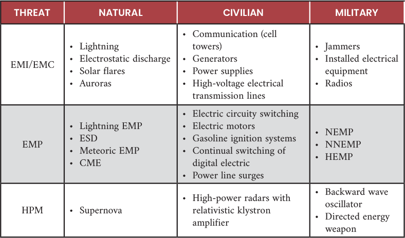
Note: EMI = electromagnetic interference, EMC = electromagnetic compatibility, and HPM = high-power microwave.
An EMP event can have cascading effects initially impacting one or more infrastructure sectors, spilling over into additional sectors, and expanding beyond the initial affected geographic region due to the interconnectivity of the various infrastructure sectors throughout the national grid. An example of cascading effects occurred on September 2, 1859, when a storm of charged particles emanating from the Sun slammed into Earth’s atmosphere, producing telegraph wire shorts and igniting widespread fires. Known as the Carrington Event, this geomagnetic storm was believed to be caused by a CME from the Sun colliding with Earth’s magnetosphere. At the time, the telegraph would have been considered state of the art. Since that time, other events impacting electrical and radio systems have been recorded in 1872, 1921, 1938, 1941, 1958, 1960, 1972, and 1989. In addition, there have been other events classified as near misses. Some of the more significant events since the Carrington event occurred in 1921 and 1989.
In 1921, a three-day geomagnetic storm, named the New York Railroad Storm, was caused by the impact of an extraordinarily powerful coronal mass ejection on Earth’s magnetosphere [1]. This storm has been classified as the most intense geomagnetic storm of the 20th century. The result of its electrical current initiated fires worldwide, including one near Grand Central Terminal New York, hence the name “New York Railroad Superstorm.” Undersea telegraph cables were adversely affected as well as telegraph systems across Europe and the southern hemisphere.
In 1989, a geomagnetic storm emanating from severe solar storms produced a 9-hr outage of Hydro-Québec’s electricity transmission system [2]. Additional storms during the same year resulted in communication blackouts; loss of control of some satellites in polar orbits; communication interruptions with the Geostationary Operational Environmental Satellite, resulting in anomalous images; and the Space Shuttle Discovery, which was aloft at the time and experienced sensor malfunctions that resolved when the solar storm subsided.
These examples demonstrate that even though there have been technology improvements in electronics and electrical systems, they remain vulnerable to effects from an EMP. Due to the greater reliance on advanced electronics and associated electrical systems with a sensitivity to EM radiation and power surges, the impact of an EMP event can be devastating to the nation’s electrical infrastructure.
To combat the deleterious effect of EMPs on the nation’s infrastructure, it is necessary to develop the tools and techniques necessary to mitigate the effects to infrastructure from any event that produces an EMP. Once implemented, these tools and techniques would minimize potential damage from the various components of an EMP event and result in an energy and communication infrastructure capable of uninterrupted operation. Without the appropriate tools, the nation’s infrastructure is at risk of being severely damaged, potentially irrevocably, compromising its ability to respond to the source of the EMP event and recover from it.
EMP Description
On March 26, 2019, presidential executive order (EO) 13865, “Coordinating National Resilience to Electromagnetic Pulses,” was signed that directs action in five areas to reduce the risk that EMPs pose to U.S. critical technology and infrastructure systems [3]. These five areas included the following:
- Identify national critical functions and associated priority critical infrastructure at greatest risk from EMPs.
- Improve understanding of EMP effects.
- Evaluate approaches to mitigate the effects of EMPs.
- Strengthen critical infrastructure to withstand the effects of EMPs.
- Improve national response to EMP events.
This EO was based on the “Electromagnetic Pulse (EMP) Protection and Resilience Guidelines for Critical Infrastructure and Equipment” report dated February 5, 2019 [4]. The report was a collaborative effort between the Department of Homeland Security Science and Technology Directorate, the Federal Emergency Management Agency Integrated Public Alert and Warning System Program, and the Cybersecurity and Infrastructure Security Agency. It summarizes recommendations that federal, state, and local agencies and private sector critical infrastructure owners and operators can employ to protect against the effects of an EMP event.
To provide protection against an EMP event, it is necessary to understand the EM environment and parameters necessary to mitigate effects from the event. Elements of the EM spectrum are provided in Table 1, where EMP is a major player. The EM threats identified in the table are frequency dependent and require differing shielding levels, as identified in Table 2. Of the three threats, the Air Force Global Stike Command (AFGSC) has recognized the need to create a robust and resilient nation that is well prepared to face EMP threats, protecting its citizens, critical infrastructure, and military capabilities [5].
Table 2. Frequency and Shielding Ranges for EM Threats

An EMP event can be challenging for electronics and electrical systems. An EMP on unprotected systems can produce upsets, hard failures, and power surges that can damage electrical and communication networks. Present systems typically have minimal protection to address low levels of EM radiation. This protects against EMI while allowing EMC with EM radiating systems like communication systems (i.e., cell towers), generators, power supplies, and high-voltage electrical lines.
EMI is the interference caused by an EM disturbance affecting the performance of a device or system which can emanate from natural and man-made sources. Natural sources of EMI include electrostatic discharge, electrical storms, solar flares, and auroras, while man-made sources include communication systems (i.e., cell towers), generators, power supplies, and high-voltage electrical lines. While natural sources may be rare and even sporadic, man-made sources of EMI are prolific in the operating environment. When insufficient protection is present, EMI often manifests itself as undesirable noise that may disrupt the proper operation of electrical, electronic, and radio frequency (RF)-dependent systems.
There are four types of EMI—conducted, common mode, differential mode, and radiated. Conducted EMI requires direct contact with a source of EMI and flows through the wires of the system. Common and differential modes define high-frequency and low-frequency EMI, respectively, flowing through conductors or adjacent wires. Radiated EMI is the most common form that results from radiating EM fields, with the most common form appearing as static noise on radio receivers and snow on TV monitors. EMC represents the ability of a system to operate in the presence of EM radiation and the ability not to generate EM radiation that can impact other nearby operating systems.
EMI/EMC frequency range is 9 kHz to 40 GHz. The shielding required to provide adequate protection is between 60 and 100 dB, as indicated in Table 2. While there is some overlapping between EMI/EMC and EMP, an EMP event affects a greater frequency range and can require greater shielding protection to provide shielding for the event. An EMP event is a form of EMI; however, it is referred to as a transient electromagnetic disturbance, characterized by a pulse of brief, high-intensity EM radiation. While there are various sources of an EMP, the most common is a GMD, whereas the most severe is associated with HEMP. As such, the parameters associated with HEMP are used to define the guidelines to provide protection for an EMP event.
As illustrated in Figure 1, there are three components associated with a HEMP event, according to the International Electrotechnical Commission [6]. They are designated as E1, E2, and E3.
![Figure 1. Types of HEMP (Source: Radasky and Savage [6]).](https://hdiac.dtic.mil/wp-content/uploads/2025/05/luzetsky-figure-1.png)
Figure 1. Types of HEMP (Source: Radasky and Savage [6]).
E1 results when gamma radiation from the nuclear event ionizes atoms in the upper atmosphere and consists of a fast, large amplitude pulse, with frequency content in the hundreds of megahertz uncommon for a natural-occurring EMP event like from a GMD. The damage resulting from E1 causes conductive objects like control cables and power lines to behave as antennae and absorb the RF pulse. Referred to as the conductive threat, the E1 field couples to overhead lines, control cables, etc., and generates conducted voltage and current transients that adversely affect connected equipment. In addition to the conductive threat, there is a radiated threat which occurs when the E1 field couples directly with equipment-inducing voltages and current transients at the circuit board level, resulting in device upset or damage. Figure 2 illustrates the differences between the conducted and radiated threats associated with the E1 waveform [7].
![Figure 2. Example of Radiated and Coupled Threat Associated With E1 (Source: U.S. Department of Energy [7]).](https://hdiac.dtic.mil/wp-content/uploads/2025/05/luzetsky-figure-2.png)
Figure 2. Example of Radiated and Coupled Threat Associated With E1 (Source: U.S. Department of Energy [7]).
The brief but intense field from E1 induces high voltage in electrical conductors, causing most of the damage through excessive electrical breakdown voltages. This single component of a HEMP can damage or disrupt electronic devices, communication systems, and control and acquisition systems. Since it changes in nanoseconds, ordinary surge protectors cannot react in an expeditious manner to provide protection. In addition, the resulting voltage surges can also cause insulation flashover of distribution-class insulators and transformers.
E2 is a lower intensity event occurring over a greater time through producing gamma rays and gammas from inelastic neutron scattering. The time pulse is intermediate, occurring from approximately 1 µs to 1 s after event initiation (i.e., explosion). The E2 aspect of the HEMP event patterns the profile associated with lightning having a lower energy-induced E2 (as illustrated in Figure 3), which overlays lightning with the pulse associated with HEMP.
![Figure 3. Types of High-Altitude EMPs With Lightning Overlay (Source: Gombosi et al. [8]).](https://hdiac.dtic.mil/wp-content/uploads/2025/05/luzetsky-figure-3.png)
Figure 3. Types of High-Altitude EMPs With Lightning Overlay (Source: Gombosi et al. [8]).
The main threat with E2 is that since it follows E1, it can produce damage to devices that would normally be protected against E2 but have been compromised from the E1 pulse. Like lightning strikes, EM fields from the E2 pulse couple through the air to overhead lines and cables, posing a threat from both radiated and conductive EMI. Since the amplitude is generally less than that associated with lightning, transmission voltage and distribution systems may have adequate lightning protection. However, some systems have less protection than others, particularly in areas that experience less lightning phenomenon than others or when protection is considered a significant cost element.
E3 differs from both E1 and E2, with a lower pulse intensity occurring over a longer time. This component of HEMP produces a geomagnetically induced current in transmission lines and bulk transformers with grounded Y-type windings. The result can be magnetic saturation that causes harmonic currents and absorbs significant quantities of reactive power, leading to hotspot heating in windings and structural components. This can translate to direct impacts to the electric power grid and result in voltage collapse (regional blackout), protective equipment failure from harmonics, and transformer damage due to heating above from the design. In addition, certain sensitive electronics may also be prone to damage or disruption from harmonic voltage distortion transferred from the voltage transmission system to medium- and low-voltage systems.
EMP Mitigation and Protection
Protecting elements of the infrastructure from the effects of EMP requires addressing the three pulse elements (E1, E2, and E3) associated with a HEMP event. With this approach, most of the main effects associated with an EMP are mitigated. Methods to protect against the effects of EMP require a layered approach comprised of four distinctive layers: (1) isolation, (2) EMP/HEMP filtering, (3) surge protection, and (4) EM shielding [9].
Isolation
This is the most assured method for protecting against EMP; however, it is the least practical in totality for various aspects of the U.S. infrastructure. For isolation to be totally effective, the isolating structure must be sized sufficiently to shield EM radiation and be free of penetrations or cabling passthroughs that result in point of EM entrance, either directly or through traversing conductive cabling like power lines. Essentially, the structure acts like a giant all-encompassing faraday cage. Many aspects of the electrical infrastructure cannot take advantage of isolation, such as transformers, power stations, communication hubs, computing systems that utilize the internet, and satellite links. However, where possible, isolation can be used to reduce some of the EMP magnitude-lessening impact on infrastructure elements.
EMP/HEMP Filtering
This is a device that is placed in line with the power line designed to suppress HEMP waveforms in the power line. The operating feature of an EMP/HEMP filter is a suppression circuit exhibiting a high off-state impedance during its normal operation, which is transparent to circuits further down the line from the filter. In case of a voltage overshoot exceeding the filter-switching voltage, the filter suppression circuitry switches to a very low-impedance, high-attenuation mode that shorts out the excessive voltage and absorbs the excess energy. During the duration of the high-voltage event, the EMP/HEMP filter maintains suppression until a voltage drop decreases to a level below the switching voltage deemed to be safe [10].
It is important to distinguish EMP/HEMP filtering over EMI/EMC filters typically used for commercial applications. While protection is afforded by some EMI/EMC filters for the waveforms associated with E1, E2, and E3 phases of an EMP/HEMP event, they cannot defend against the power levels and fast transients associated with E1 and E2 waveforms. In addition, the EMI/EMC filters typically do not have the ability to provide adequate suppression over 80 dB of attenuation from 10 MHz to 10 GHz [10]. EMP/HEMP filtering is designed to focus on the E1 power levels and fast transient associated with the E1 phase of the EMP/HEMP event, while surge protection can be used to address the E2 phase, as the power and transient levels mirror that associated with a lightning event.
Surge Protection
As illustrated in Figure 2, while the E2 phase of an EMP/HEMP event results from radiation interactions with the atmosphere, its waveform, power levels, and time transients closely resemble the effects associated with lightning. Although the induction effects are different than a direct lightning strike on power lines or electrical systems, the use of adequately sized surge protectors can mitigate the impact to electrical systems as well as those systems downstream from a power surge, such as that from a direct lightning strike. Surge protectors utilize grounding wires to divert power levels that exceed the design level to the suppressor’s grounding wire. The actual method of execution differs with various arrestor designs, but the premise is the same. Suppressors use two basic circuit designs—a parallel design and a series design. The parallel design diverts excess electricity away from the standard path to another circuit, while a series design does not shunt excess electricity away from the standard path but retards its progress through the hot line. In a series design, excess voltage is detected, stored, and gradually released. It is argued that the series design reacts more quickly and does not direct the excess to the ground line, thereby potentially upsetting or disrupting the electrical system feeding the components impacted.
As a backup to surge protectors, built-in fuses are often used. Once the current exceeds a specified level, the resulting heat burns the fuse breaking the circuit and curtailing continued movement of the power surge through the line to the protected equipment. The fuse works once, and while the functionality of the protected equipment is spared, the operation is disrupted until fuses are replaced.
EM Shielding
This addresses all three phases of the EMP/HEMP event (E1, E2, and E3) by blocking EM radiation across all frequencies regardless of power levels and transient times when properly designed. EM shielding provides passive protection against direct absorption effects of EM waves for equipment and power systems enclosed by the shielding. Various materials with different weights, sizes, and costs are available, as well as the various levels of protection afforded by the materials. Considering other protection features, the level of protection can be sized to the electrical systems and protected equipment. In some instances, shielding may be designed to reduce the EM radiation to a level that can be easily handled by other techniques like EMP/HEMP filters and surge protectors. EM shielding can be integrated into new construction and retrofitted to existing structures.
The common shielding methodology involves constructing boxes or enclosures for electronic systems that require protection with highly conductive metallic materials. When properly sized from a thickness perspective, these systems can yield EM shielding levels across the entire frequency spectrum of 90 dB, with peaks above 120 dB and an approximate average of 100 dB (as shown in Table 2). The most common material for these enclosures is copper; however, aluminum and steel are also used. More exotic metals are employed when magnetic effects are of concern. Large structure like buildings can be shielded with metal sheeting, foils, conductive paint, and conductive concrete (emerging technology). When considering the shielding methodology, weight and cost implications must be considered.
Emerging technologies explore the application of nonmetallic materials, especially composites [11]. These technologies offer a lower weight alternative to metallic structures and a versatility to customize the shielding for various structure configurations. Figure 4 illustrates some of these advancements, but their performance is typically less than that realized by metallic structures.
![Figure 4. EM Shielding Effectiveness of Different Materials (Source: Piner et al. [11]).](https://hdiac.dtic.mil/wp-content/uploads/2025/05/luzetsky-figure-4.png)
Figure 4. EM Shielding Effectiveness of Different Materials (Source: Piner et al. [11]).
A recently developed multifunctional composite material has been developed with EM shielding properties like that associated with a 1/8-in-thick aluminum enclosure box, as shown in Figure 5. The material exhibited EM shielding effectiveness levels across all frequencies of the EM spectrum, exceeding those levels of other existing composite materials (see Figure 4), and a shielding effectiveness comparable to an aluminum enclosure [12]. When compared to an identically sized enclosure, the developed composite material achieved a comparable EM shielding level at a weight ~24% of that of the aluminum (1/8-in-thick) enclosure.
![Figure 5. Shielding Effectiveness of Multifunctional Composite and Aluminum Enclosures (Source: Luzetsky et al. [12]).](https://hdiac.dtic.mil/wp-content/uploads/2025/05/luzetsky-figure-5.png)
Figure 5. Shielding Effectiveness of Multifunctional Composite and Aluminum Enclosures (Source: Luzetsky et al. [12]).
Finally, grounding, also known as earthing, is necessary to provide a safe path for excess electricity to escape to the ground. Without grounding, electricity can build up in the wires or electrical devices and cause irreparable damage.
Conclusions
EMP protection, from natural and man-made events, is critical for the electrical infrastructure in the United States. Historically, past events have shown that a GMD can and has disabled electrical systems regionally and globally. With the greater proliferation and reliance on electrical systems, the impact on the infrastructure can have cascading effects that disable water systems, shut down the electrical grid and computing systems, disrupt communications, and result in societal unrest.
Fortunately, there are techniques to mitigate the effects, and the government recognizes the problem; however, implementation has been slow to affect appropriate modifications. While there is significant work being done to develop advanced EMP shielding techniques, this work has largely centered on the military aircraft industry. There has been an increased interest in transferring this technology to the country’s electrical and electronic infrastructure. This increased interest is evidenced by the involvement and directives from the AFGSC for EM protection of the country’s infrastructure and by the release of Small Business Innovation Research (SBIR) AF233-0036 titled “Commercial Technologies for EMP Hardening and Electrical System Protection” [13], which highlights EMP protection technology.
References
- Phillips, T. “The Great Geomagnetic Storm of May 1921.” Spaceweather.com, 12 May 2020.
- Boteler, D. H. “A 21st Century View of the March 1989 Magnetic Storm.” Space Weather, AGU (Advancing Earth and Space Sciences), vol. 17, issue 10, pp. 1427–1441, 10 October 2019.
- Federal Register. Presidential EO 13865 – “Coordinating National Resilience to Electromagnetic Pulses.” Executive Office of the President, The Daily Journal of the Federal Government (National Archives), vol. 84, no. 61, 29 March 2019.
- National Coordinating Center for Communications. “Electromagnetic Pulse (EMP) Protection and Resilience Guidelines for Critical Infrastructure and Equipment.” Version 2.2, National Cybersecurity and Communications Integration Center, Arlington, VA, 5 February 2019.
- U.S. Department of the Air Force. Instruction 10-2601 – “Electromagnetic Pulse Survivability Program,” p. 29, 11 January 2022.
- Radasky, W., and E. Savage. “High-Frequency Protection Concepts for the Electric Power Grid.” Meta-R-234, Metatech Corporation, prepared for Oak Ridge National Laboratory, January 2010.
- U.S. Department of Energy. “High-Altitude Electromagnetic Pulse Waveform Application Guide.” CESER Technical Analysis Report, Office of Cybersecurity, Energy Security, and Emergency Response, July 2023.
- Gombosi, T. I., D. N. Baker, A. Balogh, P. J. Erickson, J. D. Huba, and L. J. Lanzerotti. “Anthropogenic Space Weather.” Space Science Review, 24 March 2017.
- The National Institute of Building Sciences. “High Altitude Electromagnetic Pulse (HEMP) Effects and Protection.” Whole Building Design Guide (WBDG), https://www.wbdg.org/resources/high-altitude-emp-effects-protection, accessed on 17 November 2024.
- API Technologies Corp. “EMP/HEMP Filters: New Electronics Assembly Level Solution in the Battle Against Intentional EMI and Electronic Warfare.” EMP/HEMP Filters: New Electronics Assembly-Level Solution in the Battle Against Intentional EMI and Electronic Warfare, accessed on 4 November 2024.
- Piner, R., D. Motes, and T. Kneen. “Development of EMI Shielding Capabilities of Fiber Reinforced Composites.” DSIAC Technical Inquiry (TI) Response Report, February 2022.
- Luzetsky, H. R., M. Klein, and G. Ostrander. “Multifunctional Structural Composite With Integrated Electromagnetic Shielding.” Vertical Flight Society 73rd Annual Forum and Technology Display Conference, Multifunctional Structural Composite with Integrated Electromagnetic Shielding, 8 May 2017.
- U.S. Department of Defense. “Commercial Technologies for EMP Hardening and Electrical System Protection.” SBIR AF233-0036, 2023.
Biography
Harry R. (“Rick”) Luzetsky is a subject matter expert in composites and survivability at SURVICE Engineering Company’s Aberdeen Research Organization – Research and Analysis Group. He currently supports the U.S. Army Evaluation Center in the survivability assessment of military platforms and has been involved in developing a ballistic-tolerant composite drive shaft, armored actuators, a thermoplastic tail cone, and a multifunctional composite material with structural and integrated EM shielding capabilities for military platform structures. He has over 40 years of experience with vertical lift aircraft, specializing in composite materials and survivability technology enhancements to improve platform performance. He holds two autonomous, self-sealing, fuel bladder patents. Mr. Luzetsky holds a B.S. in materials engineering from Drexel University.